| Quantity: | |
|---|---|
| min order: 1 | |
| View wholesale prices
| |
")
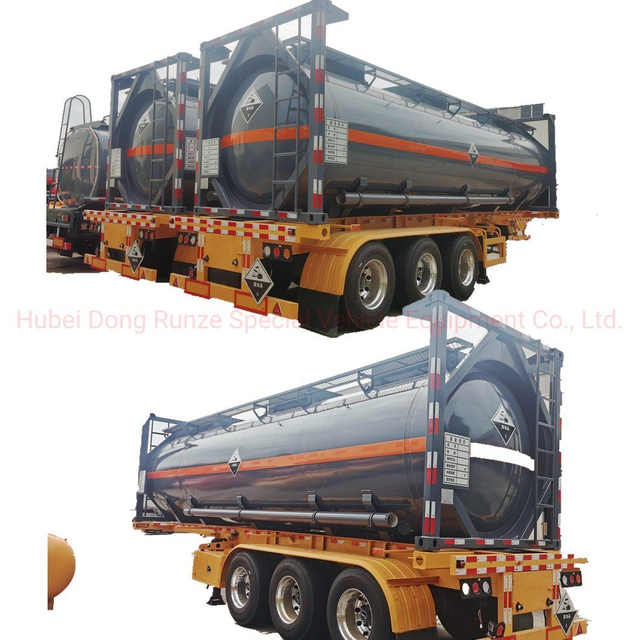
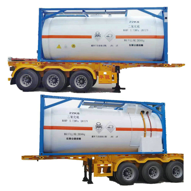
| SPECIFICATION NO : FF3A-26-T11-L4BN-SPIC-P21067 | |||||||
| TANK TYPE | Full Frame T11 UN Portable tank | ||||||
| 1. General Parameters 1.1 Design Code ASME VIII DIV. 1 / EN 14025 1.2 Maximum Gross Mass 36000 kg 1.3 Nominal Capacity 26000 litre (0, - 1.5%) 1.4 Vessel Design Temperature -40°C to +150 °C 1.5 Maximum Product Loading Temperature (atm .) 150 °C 1.6 Maximum Allowable Working Pressure4.0 bar Hydrostatic Test Pressure 6.0 bar Maximum External Pressure 0.41 bar 1.7 Tare Mass 3560 kg (± 3%) 1.8 Frame (length / width / height) 6058 / 2438 / 2591mm 2. Tank Details | |||||||
| 2.1 | Shell | Material Thickness Finish Material Thickness Finish | SANS 50028-7 Type 1.4402/1.4404 (C≤0.03%) Equivalent to 316L 316L Minimum calculated thickness: 4.2mm Corrosion allowance: 0.2mm Manufacture Thickness: 4.4mm SANS 50028-7 Type 1.4402/1.4404 (C≤0.03%) Equivalent to 316L 316L Minimum calculated thickness: 4.7mm Corrosion allowance: 0.2mm Manufacture Thickness: 4.9mm (after forming) Hot or Cold Rolled and polished with 120 grit | ||||
| 2.2 | Ends | ||||||
| 2.3 Welds Shell | Longitudinal: as welded. Circular: As welded, Bottom 400mm flush and polished (120grit). Ground flush and polished with 120 grit . 3-off stainless steel channel section. | ||||||
| 2.4 Stiffening Rings | |||||||
| 2.5 Radiography 2.6 Steam Heating | As per code requirements 8-off longitudinal runs steam heating system on barrel. The longitudinal steam runs manufactured from stainless steel. The steam heating connectors will be 304 grade . The tank vacuum rings not used for steam heating. 1” BSP inlet, 1” BSP outlet both with captive caps and cable. 4 bar working pressure, 6 bar test with warning decals and markings. A 3/8” condensate drain ball is fitted at the lowest position of the outlet. Rockwool (50kg/m³) 50mm thick on aluminium foil. 1.8mm GRP prepainted White (RAL9010) with lapped joints. Seal provided by sealant. 10mm drain hole per panel on bottom centreline. 2.0mm thick GRP one piece end (RAL 9010). 2-off Stainless steel 304 2.0mm thick boxes fitted. Front spillbox contains manhole and safety relief. Rear spillbox contains air inlet and top discharge provision. Each box is equipped with 2-off DN25 surface mounted PVC drain tubes fitted to opposite end of box. No lids fitted but provision for future fitting is provided. One stainless steel 304 1.5mm thick bottom valve cabinet is fitted around the bottom discharge assembly. No Lid and bottom plate to be fitted.。 | ||||||
| 2.7 Insulation Shell Ends 2.8 Cladding Shell Ends 2.9 Spillbox | |||||||
| 2.10 Bottom Valve cabinet | |||||||
| 3. Frame Details 3.1 Type | Full frame beam design ISO 1496/3 (1CC) without saddles. Front | ||||||
| and rear frame with lowered horizontal bottom crossmembers. SPA-H or equivalent. SPA-H ISO 1161 8-off in total. | |||||||
| 3.2 Material 3.3 Corner castings | |||||||
| 3.4 Top rails 3.5 Protection Top Bottom 3.6 Ladder | Integral in frame design. 4-off per tank, 1 per corner on top rail and header. Raised bottom rail, lowered front and rear sill. 300mm wide Stainless steel 304 ladder, fitted to the rear end right hand side. Ladder rungs to be antislip type. Fasteners to be stainless steel welded to prevent theft.. 1-off full length longitudinal and 2-off transverse 475mm wide aluminium type(F-style). Walkway supported off spillboxes and end frames using stainless steel fastenings with nuts. | ||||||
| 3.7 Walkway | |||||||
| 3.8 Earthing Protection 1-off stainless steel lug fitted to rear end bottom of frame. 3.9 Painting Carbon steel shotblasted to Sa 2½ profile First layer Epoxy zinc rich primer 30 microns min DFT Second layer Epoxy primer 40 microns min DFT Final layer Acrylic 50 microns min DFT Total 120 microns min DFT Colour Blue (RAL 5002) | |||||||
| 4. Tank Fittings 4.1 Manhole | 1-of 500mm low profile, 8 point fixing with brass handnuts and TIR-locking. Gasket: Composite seal with PTFE outer encapsulating EPDM inner. 1-of. DN80 flanged Supermaxi Highflow, without flameproof gauze. Pressure only model set at +4.4 bar (63.8psi). Provisional space for the future fitting of a bursting disc and pressure gauge. The assembly is situated off centre on a tangential tank pad. Tank pad to be single drilled: 4xM16 on 152.4 PCD . | ||||||
4.2 Safety Relief Assembly | |||||||
| 4.3 Air Inlet assembly | 1-of DN 40 ball valve terminating with 1½” BSP connection and cap. The assembly is situated off centre on a tangential tank pad. Tank pad to be single drilled: 4xM10 on 103.4PCD. 1-off DN80 stainless steel tank pad fitted with a blind flange . Siphon tube support bracket to be fitted on tank bottom . The assembly is fitted off centre on a recessed horizontal tank pad. Tank pad to be dual drilled: 6xM12 on 168PCD and 4xM16 on 160PCD. 1-of DN80 45° hi-lift Footvalve and 3” clamped butterfly vale terminating with a 3” BSP spigot with cap and chain. Tank pad to be single drilled: 8xM12 on 177.8PCD. A plastic coated stainless steel cable is fitted to the entire length of the right hand side of the tank . 1-off emergency decals are fitted above the cable . Not fitted. Provision for a fusible link is fitted to the remote control cable. A surface mounted analogue type is fitted on rear GRP end left hand side of the tank . Dual scale -40°C to + 160°C / -40°F to 320°F. The thermometer is fitted with a protection bar. A clear plastic document holder ø 110mm is fitted to the rear right hand side beam . A drain hole is provided at the lowest point. One set of mandatory decals is fitted . Customer logo supplied and fitted by manufacturer. One set of stainless steel single language data plate is provided stating the requirements as per the code. | ||||||
| 4.4 Top Discharge Prov. | |||||||
| 4.5 Bottom Discharge | |||||||
| 4.6 Remote Control | |||||||
| 4.7 Fusible Link | |||||||
| 4.8 Thermometer | |||||||
| 4.9 Document holder | |||||||
| 4.10 Decals | |||||||
| 4.11 Data Plates | |||||||
| 4.12 | Calibration | A calibration plate marked in cm/litres is fitted on the front spillbox side wall adjacent to the manhole. No calibrated stainless steel grade dipstick and bracket fitted | |||||
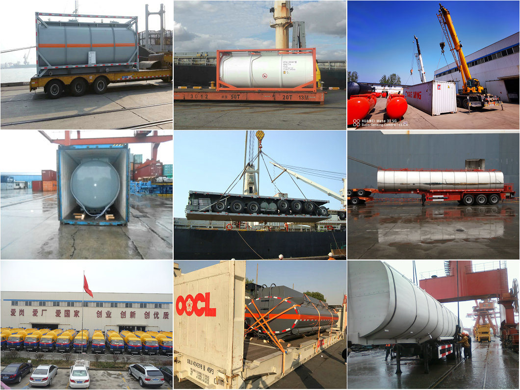
ISO 40' LNG Tank Container | Bitumen tank container | ISO 20' Tank Container |
IMO 1 | IMO 2 | IMO 5 |
1.Are you trading company or manufacturer ?
We are Group Corporation manufacturer ,have Group Factories Contractor.Don't worry,dear.We have joined the trade assurance,if the products have quality problems when you received them,the payments can be refund to you.